
Parabolic Equation


Developed by Hsu & Evans (1989) through a series of scaled experiments, the equation is based on a relationship between geometric characteristics of the beach and the angle of incidence of predominant waves. For the application of the equation, the following parameters are extracted through a satellite image, aerial photo, or map for the resolution of Equation 01.

Parameters:
R0 or Rβ (control line or initial radius): a line connecting the wave diffraction point to the end point of the straight part of the beach;
Crest line of the predominant waves: the extraction of the obliquity of the predominant waves on the bay beaches is obtained through aerial images or maps, corresponding to a line parallel to the straight part of the beach, which is transferred from the diffraction point;
R: Radii drawn from the promontory (diffraction point), joined along the beach. Extracted from the angle θ and the crest line of the predominant waves;
β (beta angle): the angle formed between the crest lines of predominant waves and the control line R0;
θ (theta angle): the angle formed between the crest line of predominant waves and the other radii R;
C0, C1 and C2: obtained based on the beta angle and defined through tabulated tests and experiments (Hsu & Evans, 1989).
For this equation, the polar coordinate system is used, and due to the ratios, the equation is dimensionless.
- Manual Application of the Equation:
To apply the parabolic model using a map, topographic charts, vertical aerial photography, or satellite image of a beach, the following general steps should be followed. It is emphasized that the equation is dimensionless, regardless of the scale of the maps or topographic charts.
With this material in hand, proceed as follows:
- Determine the wave diffraction point and the final point of the beach;
- Draw R0 (linha de controle), (control line), draw a line from the point where wave diffraction occurs to the final point of the beach and measure the length of this line to obtain R0;
- Draw a line on the straightest part of the beach and connect this line to the diffraction point with a parallel ruler or set square, with the angle formed between them referred to as beta angle, measured in degrees, or draw the crest line of the predominant waves and transfer it (parallelly) to the point where this line intersects the control line;
- For the R radii, using a protractor, draw lines at 10-degree intervals (up to 150 degrees) from the point of wave diffraction to other points on the periphery of the beach while there is sand. Thus, the R radii are obtained for each theta angle formed.
- For the R radii, using a protractor, draw lines at 10-degree intervals (up to 150 degrees) from the point of wave diffraction to other points on the periphery of the beach while there is sand. Thus, the R radii are obtained for each theta angle formed.
- The length of the R radii is determined by applying Equation 01, with C0, C1 e C2 obtained in relation to the beta angle, and their values are tabulated.
- After calculating all the lengths of the R radii, connect the ends of these radii to obtain the theoretical coastline for the respective beaches.
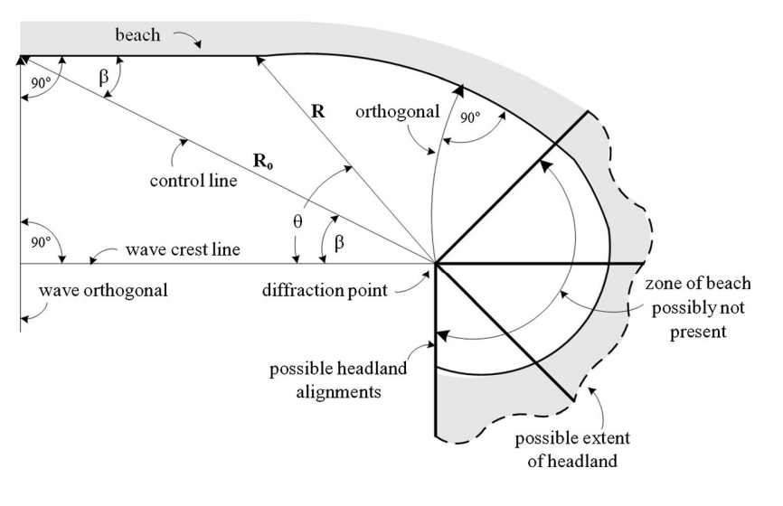 Figura: Sketch of a bay beach according to the parabolic approach. Source: Lausman et al. (2010)
- Applying the equation assumes that:
- Célula fechada, não há entrada nem saída de sedimentos;
- The straight segment of the beach (the sector most exposed to wave action) is normal to the crests of the predominant waves;
- The bathymetry between the two ends of the beach is uniform;
- Waves break simultaneously along the beach;
- Liquid sediment transport along the coast is zero on a historical scale.
- Considerations:
With the application of the equation and basic knowledge, the user can identify whether the beach is in a state of static equilibrium, where no morphological changes occur, or dynamic equilibrium, where morphological changes occur. It is also known that the application of this equation takes time, and with the aim of facilitating and expediting this resolution, the MepBay application was developed to enable the user a quick solution to the parabolic model, enabling testing of various beach conditions between existing and theoretical situations.
REFERENCES:
- Hsu, J. R-C., Evans, C. Parabolic Bay Shapes and Applications. In: Institution of Civil Engineers – Part 2, Londres. Proceedings… Londres: Thomas Telford, p.557-570, 1989.
- Silvester, R., Hsu, J.R.C. Coastal Stabilization: Innovative Concepts. Prentice-Hall, Englewood Cliffs, NJ. 578 pp. 1993
- Lausman, R.; Klein, A. H.F.; Stive, M.J.F. Uncertainty in the application of the parabolic bay shape equation – Part 1. Coastal Engineering, v. 57, n. 2, p. 132-141, 2010.

